Design the facility as one system.
AI infrastructure brings together compute, electrical distribution, cooling and reliability. LIZO Blueprint helps engineering teams connect those design decisions in one structured model, evaluate constraints and compare alternatives before committing to a configuration.
The complexity is in the connections.
A data centre is not an isolated collection of racks, switchboards, transformers and cooling equipment.
Changes in compute density influence electrical capacity. Electrical distribution affects which loads can be supported. Cooling assumptions determine thermal headroom. Redundancy requirements change the equipment configuration and the capacity available during maintenance or failure.
When these decisions live in disconnected tools, their assumptions and revisions can drift apart.
LIZO Blueprint provides a structured engineering-model workspace that makes the relationships between modeled systems explicit.
Conceptual design — explanatory diagram, not a product screenshot.
One connected model for engineering decisions.
Equipment hierarchy
Organise infrastructure into site, building, data hall, rows, racks and connected electrical and mechanical equipment — the hierarchy the model actually stores.
Evidence: workspace screenshot →Structured design workspace
Inspect equipment, edit supported properties and manage terminal definitions through the existing engineering interface.
Evidence: asset inspector →Constraint-based calculations
Calculate values using configured parameters and deterministic rules. Identify capacity violations and missing information — values that are not supplied are shown as MISSING, not guessed.
Evidence: validation and calculations →Scenario comparison
Compare supported changes against a baseline revision while preserving the original configuration.
Evidence: scenario comparison →Traceable engineering outputs
Reports record the revision hash they were generated from, and values are tagged as valid, assumed or missing so reviewers can see what a conclusion rests on.
Evidence: design summary report →Not offered as existing capabilities: certified protection or arc-flash analysis, iterative AC load flow, live hardware monitoring or control, protocol connectors (S7, BACnet, Modbus TCP, MQTT are modelled as “not implemented”), and automated construction design. Electrical studies in the AI-factory workspace are screening-level methods and require engineering review.
Designed for the systems behind AI infrastructure.
Modular deployment units
The AI-factory workspace represents repeatable deployment units and scalable units, so a change to unit capacity is evaluated across every instance instead of as unrelated designs.
Electrical distribution
Connect configured sources, transformers, switchboards, busways and rack feeds on a single-line diagram. Implemented checks include capacity loading, unit-checked power arithmetic, screening voltage drop and IEC 60909-style maximum three-phase short-circuit screening where impedance data is supplied.
Compute and cooling consistency
Modeled rack demand is carried into thermal assumptions; the workspace flags where configured IT heat exceeds the cooling capacity that has been entered, and leaves capacity MISSING where no value is supplied.
Resilience and energy scenarios
Explore N-1 equipment failures, fault isolation and restoration (FLISR) steps, battery energy balance and grid power-limit scenarios. These are modeled scenarios — not evidence of certified availability or real-world operating performance.
The Siemens DSX Vera Rubin NVL72 reference architecture is an example of the complexity that motivates this workflow; the workspace includes a reference template whose populated values cite the public brochure page they come from. LIZO does not supply Siemens hardware and does not reproduce a certified Siemens design.
Reference architectures inform the modeling approach. Each project requires its own equipment data, assumptions and engineering validation.
See the model, not just the promise.
Every image below is a browser capture of the running LIZO Blueprint application. Projects shown are synthetic demonstration models — the application labels them as such on screen.
Synthetic dataIllustrative demonstration data — not live facility telemetry.
Proof A · Engineering workspace
A synthetic multi-hall facility open in the editor: the project hierarchy (site → building → data hall → rows → racks) on the left, the building layout with power and cooling connections in the canvas, and the live validation panel below.
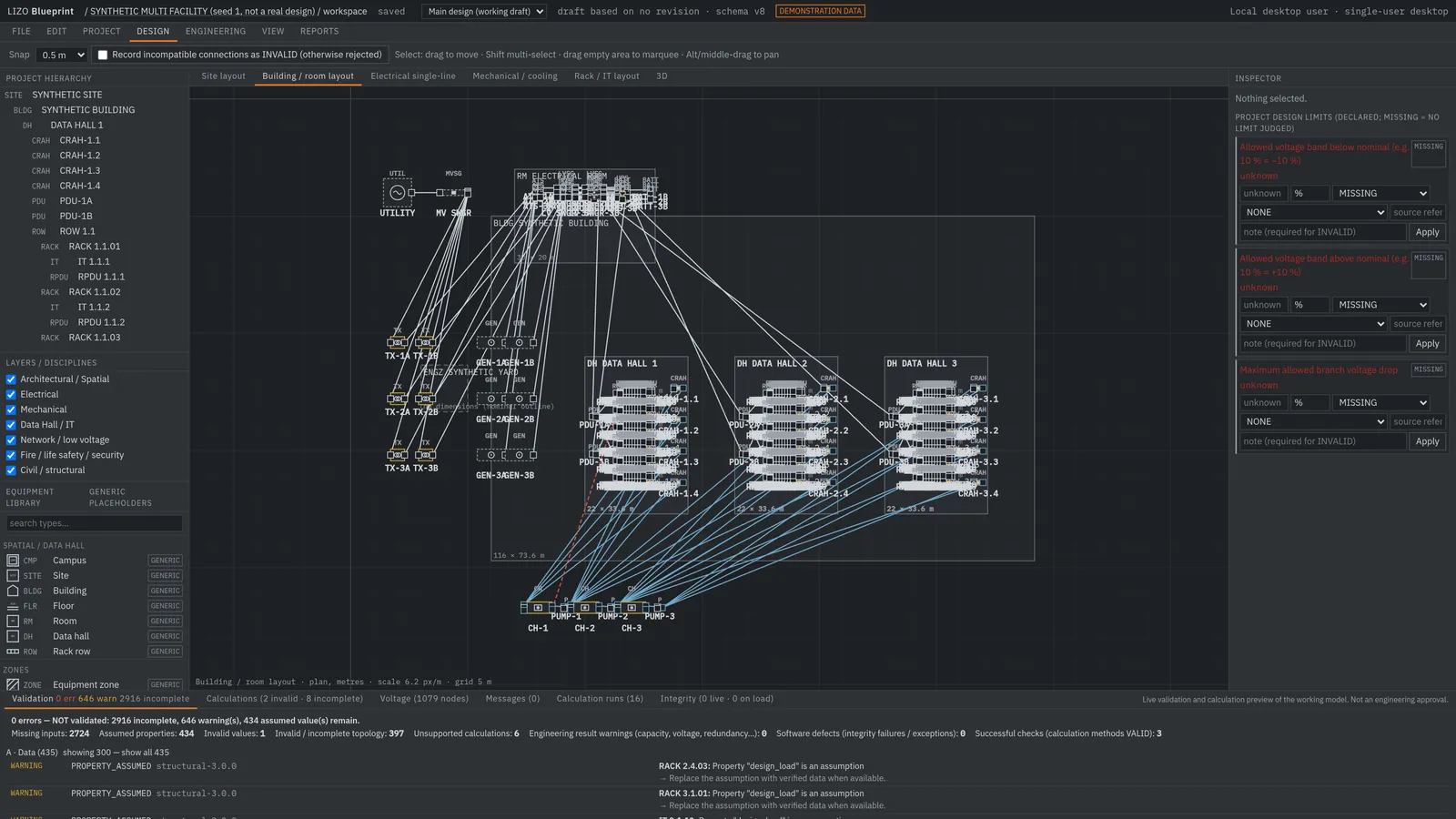
Real editor screen. The project is labelled DEMONSTRATION DATA in the app.
Proof B · Property and terminal editing
Selecting a modeled asset opens the inspector, where its supported properties and terminals can be reviewed and edited. Each value carries its status (valid, assumed or missing).
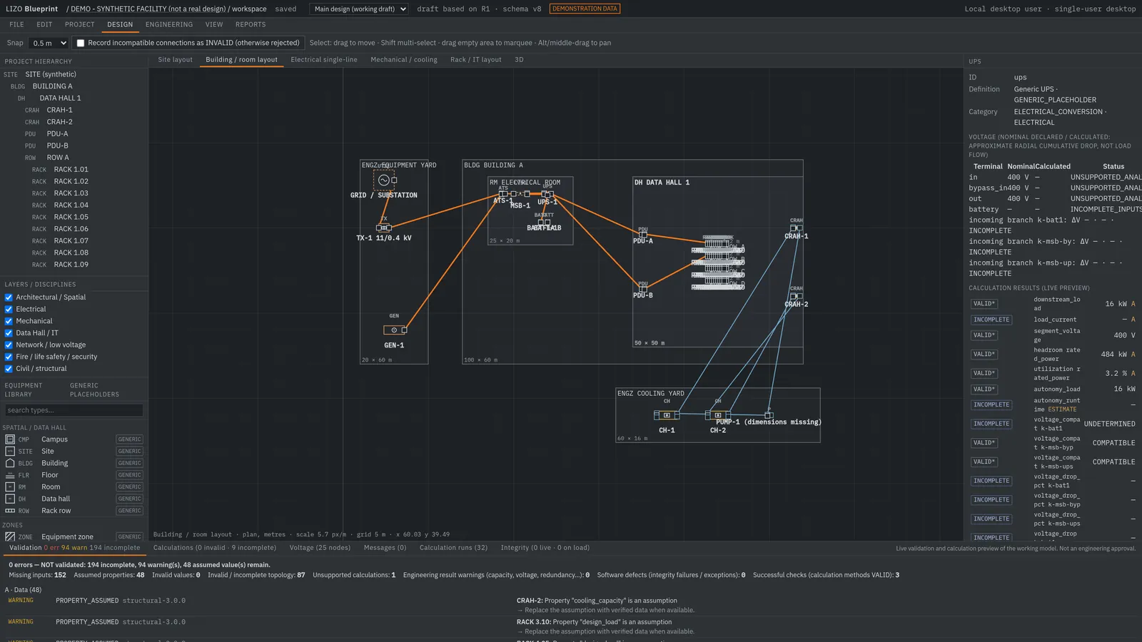
Real inspector screen on the synthetic demonstration project.
Proof C · Constraint evaluation
Calculations run deterministically on configured parameters. The validation view lists invalid values, incomplete topology and unsupported calculations, and the calculations view shows each calculation run with its inputs.
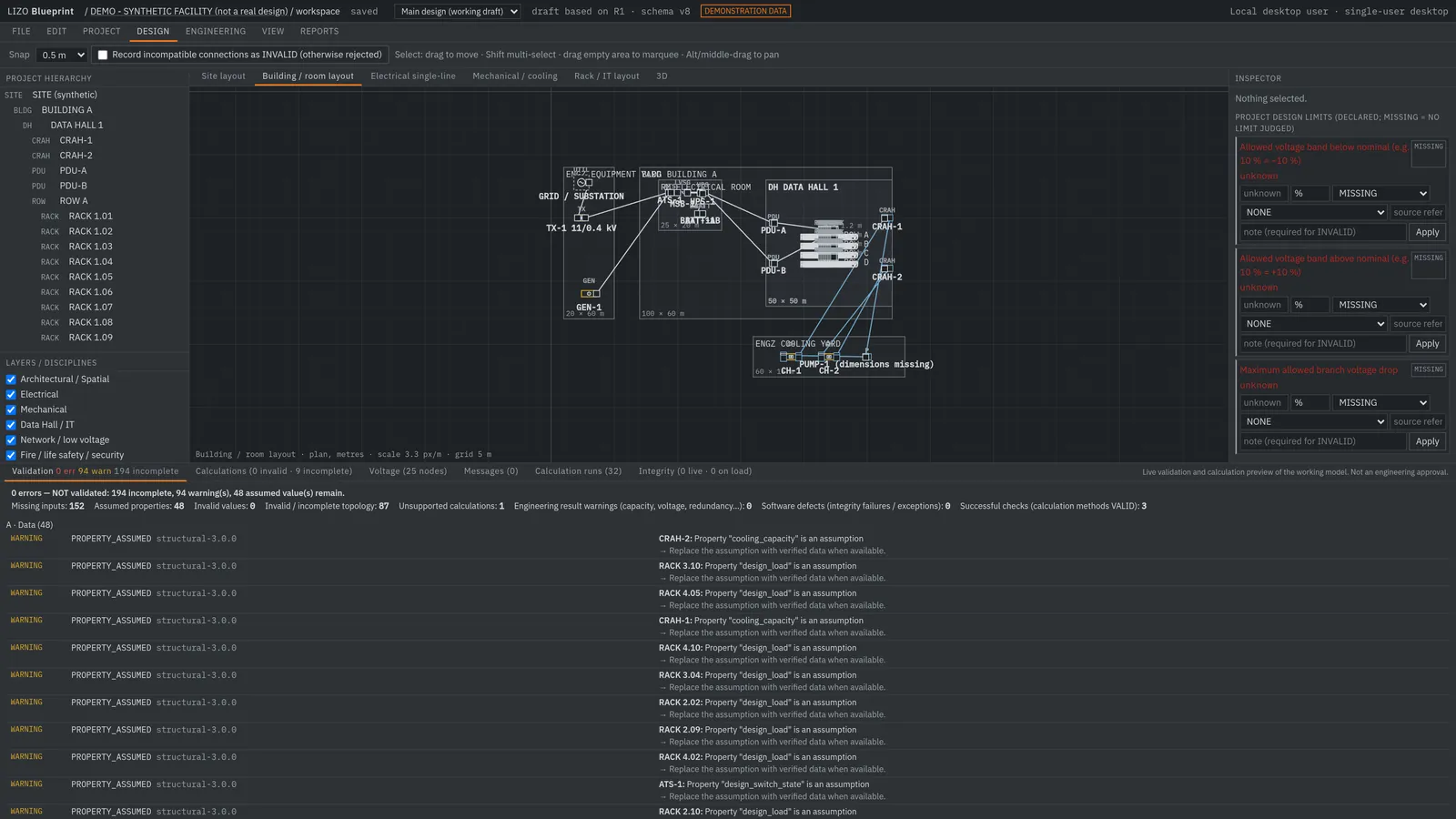
Real validation output for the synthetic model.
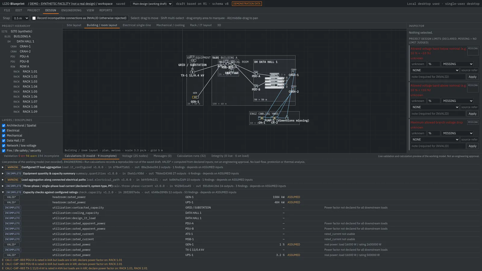
Real calculation runs on the synthetic model.
Proof D · Scenario comparison
A recorded baseline revision (R1) compared with a “high density halls” scenario: the application reports which sections changed — for example a UPS rating from 500 kW to 750 kW and rack design load from 8 kW to 12 kW — while the baseline stays intact. Both revisions are identified by hash.
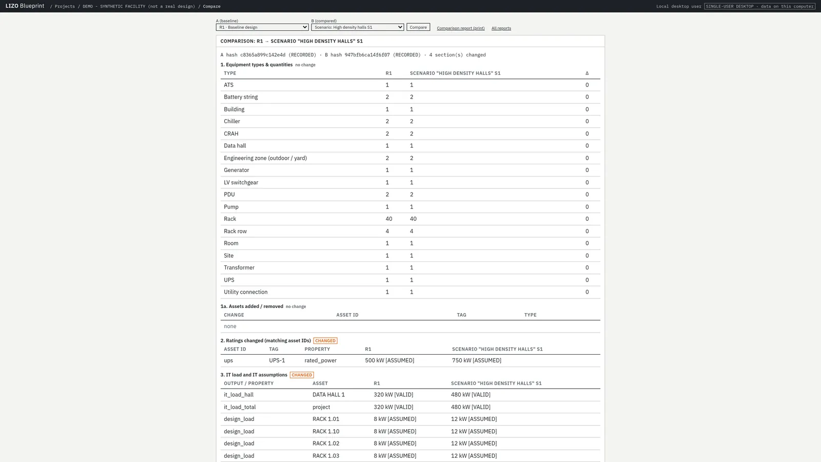
Real comparison report between two recorded revisions of the synthetic project.
Proof E · Traceable engineering output
The design summary report is generated from a recorded model revision and shows the values it was built from, including which are assumptions.
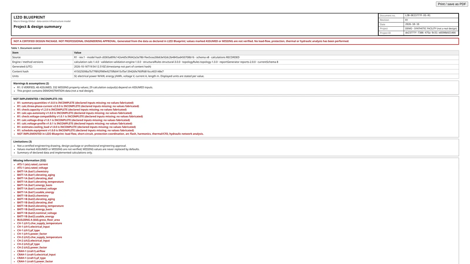
Real generated report for the synthetic project.
AI-factory workspace (DEMO template)
The AI-factory workspace inside Blueprint: single-line diagram with a transformer selected in the inspector, thermal checks and N-1 / FLISR scenario simulation. The model is the DEMO template and is badged DEMO DATA in the application.
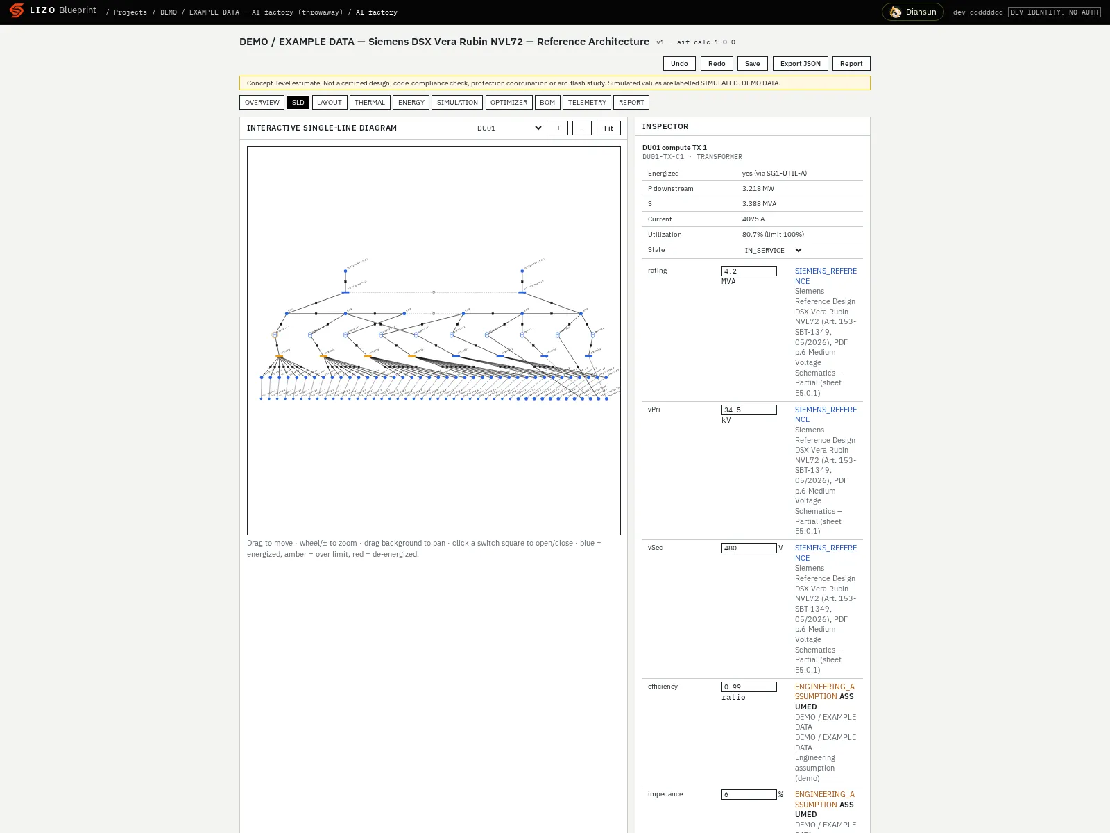
Real screen, DEMO template.
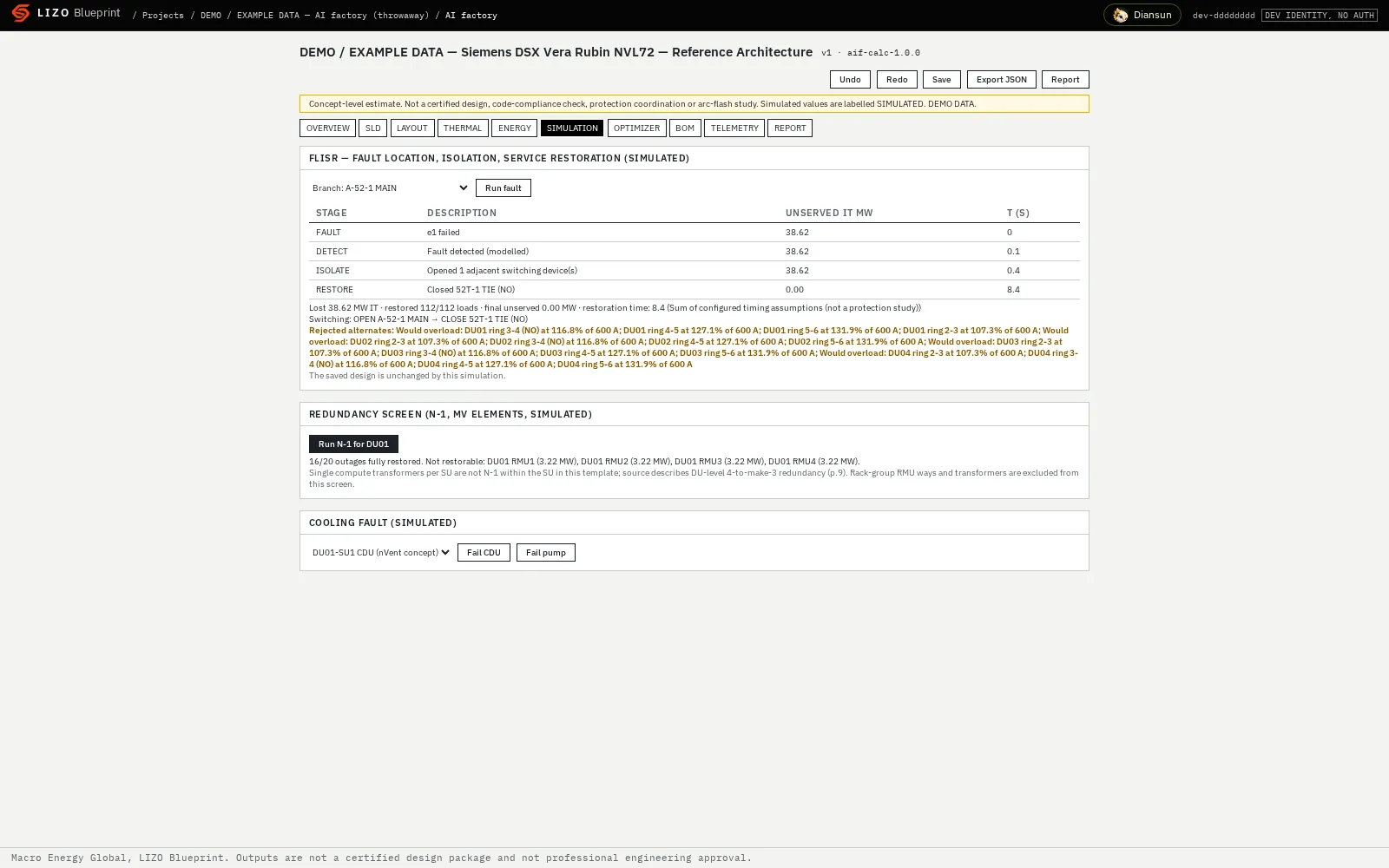
Modeled scenario on DEMO data — not measured performance.
Why no public interactive demo? The Blueprint application sits behind sign-in, and exposing its calculation engine on the public website would require a secure, isolated demo integration that does not exist yet. Rather than build a disconnected imitation, this page shows authentic captures. Request a guided demonstration.
Start with one engineering workflow.
- 01
Assess
Identify one active engineering problem, review the relevant workflow and determine the required inputs, integration boundaries and evaluation criteria.
- 02
Pilot
Scope a bounded workflow using agreed equipment data, known assumptions and a specific evaluation objective.
- 03
Evaluate
Review the resulting model, calculations, limitations and workflow fit against criteria agreed with you.